Contador con FPGA Spartan 3e
Aviso: Este post fue migrado desde mi blog viejo de mis tiempos de universitario. Cabe resaltar que, por solicitud del profesor que impartió la clase, el código aquí mostrado tiene fallos intencionales.
En ésta ocasión elaboramos un contador capaz de contar del 0 al 9999 y mostrar la cuenta en los displays. El contador tiene un botón para contar en adición, otro para contar en regresión y uno más para reiniciar el conteo a cero. Se utilizó el lenguaje VHDL para descripción de circuitos digitales.

Para el proyecto se implementó el siguiente código:
library IEEE;
use IEEE.STD_LOGIC_UNSIGNED.ALL;
use IEEE.STD_LOGIC_ARITH.ALL;
use IEEE.STD_LOGIC_1164.ALL;

use IEEE.NUMERIC_STD.ALL;

entity contador is
port (
clk: in std_logic;
btnUp: in std_logic;
btnDown: in std_logic;
btnReset: in std_logic;
vrgzaUp: in std_logic;
vrgzaDown: in std_logic;
an: out std_logic_vector(3 downto 0);
seg: out std_logic_vector(6 downto 0);
dp: out std_logic
);
end contador;

architecture Behavioral of contador is
type estados is (sumar,neutral,restar);
signal pre,fut: estados;

signal mult: std_logic_vector(1 downto 0):="00";

signal N: std_logic_vector (3 downto 0):="0000";
signal a: std_logic_vector(3 downto 0):="0000";
signal b: std_logic_vector(3 downto 0):="0000";
signal c: std_logic_vector(3 downto 0):="0000";
signal d: std_logic_vector(3 downto 0):="0000";
signal pulsoDisp: std_logic;
signal pulsoVrgza: std_logic;
signal contador1: integer range 0 to 100000 := 0;

begin
dp<='1';
 with N select
 seg<="0000001" when "0000",
    "1001111" when "0001",
    "0010010" when "0010",
    "0000110" when "0011",
    "1001100" when "0100",
    "0100000" when "0110",
    "0001111" when "0111",
    "0000000" when "1000",
    "0000100" when "1001",
  "1111111" when others;


 divisorFrecuencia: process (clk)
 begin
 if rising_edge(clk) then
  if contador1=100000 then
   pulsoDisp <= not pulsoDisp;
   contador1<=0;
  else
   contador1<=contador1 + 1;
  end if;

 end if;
 end process divisorFrecuencia;


 pro1: process (pulsoDisp)
 variable control: std_logic:='0';
 variable contint: integer range 0 to 10;
 begin
 if rising_edge(plusoDisp) then
 contint:= contint+1;
 if contint=10 then
  if (vrgzaUp='0' and vrgzaDown='0') then
   a<=a;
 elsif (vrgzaUp='0' and vrgzaDown='1') then
  a<=a-1;
  if a="0000" then
   a<="1001";
   b<=b-1;
   if b="0000" then
    b<="1001";
    c<=c-1;
    if c="0000" then
     c<="1001";
     d<=d-1;
     if d="0000" then
      d<="1001";
     end if;
    end if;
   end if;
  end if;
 elsif (vrgzaUp='1' and vrgzaDown='0') then
  a<=a+1;
  if a="1001" then
   a<="0000";
   if b="1001" then
    b<="0000";
    c<=c+1;
    if c="1001" then
     c<="0000";
     d<=d+1;
     if d="1001" then
      d<="0000";
     end if;
    end if;
   end if;
  end if;
 elsif (vrgzaUp='1' and vrgzaDown='1') then
  a<=a;
 end if;

 end if;
 mult<= mult+1;
  if (btnUp='0' and btnDown='0') then
    if btnReset='1' then
    a<="0000";
    b<="0000";
    c<="0000";
    d<="0000";
   end if;
  control:='0';
 elsif (btnUp='0' and btnDown='1') then
  if control='0' then
  a<=a-1;
  if a="0000" then
   a<="1001";
   b<=b-1;
   if b="0000" then
    b<="1001";
    c<=c-1;
    if c="0000" then
     c<="1001";
     d<=d-1;
     if d="0000" then
      d<="1001";
     end if;
    end if;
   end if;
  end if;
  end if;
  control:='0';
 elsif (btnUp='1' and btnDown='0') then
  if control='0' then
  a<=a+1;
  if a="1001" then
   a<="0000";
   b<=b+1;
   if b="1001" then
    b<="0000";
    c<=c+1;
    if c="1001" then
     c<="0000";
     d<=d+1;
     if d="1001" then
      d<="0000";
     end if;
    end if;
   end if;
  end if;
  end if;
  control:='1';
 elsif (btnUp='1' and btnDown='1') then
  a<=a;
 end if;
 end process pro1;

 pro2: process (mult)
 begin
 if mult="00" then
   N<=a;
   an<="0001";
  elsif mult="01" then
   Na<=b;
   an<="0010";
  elsif mult="10" then
   Nb<=c;
   an<="0100";
  elsif mult="11" then
   Nc<=d;
   an<="1000";
  end if;
 end process pro2;

end Behavioral;
El código tiene un control de rebote para los botones. También se integraron interruptores con la función de realizar un conteo continuo.
Para el mapeo de entradas y salidas se utilizó el siguiente código UCF. El código contiene el nombre la ubicación fija de todas las entradas y salidas, de ésta manera asociamos físicamente los pines.
NET "clk"   LOC = "B8"; # Bank = 0, Pin name = IP_L13P_0/GCLK8, Type = GCLK, Sch name = GCLK0

NET "seg<6>" LOC = "L18"; # Bank = 1, Pin name = IO_L10P_1, Type = I/O, Sch name = CA
NET "seg<5>" LOC = "F18"; # Bank = 1, Pin name = IO_L19P_1, Type = I/O, Sch name = CB
NET "seg<4>" LOC = "D17"; # Bank = 1, Pin name = IO_L23P_1/HDC, Type = DUAL, Sch name = CC
NET "seg<2>" LOC = "G14"; # Bank = 1, Pin name = IO_L20P_1, Type = I/O, Sch name = CE
NET "seg<1>" LOC = "J17"; # Bank = 1, Pin name = IO_L13P_1/A6/RHCLK4/IRDY1, Type = RHCLK/DUAL, Sch name = CF
NET "seg<0>" LOC = "H14"; # Bank = 1, Pin name = IO_L17P_1, Type = I/O, Sch name = CG
NET "dp"     LOC = "C17"; # Bank = 1, Pin name = IO_L24N_1/LDC2, Type = DUAL, Sch name = DP

NET "an<0>" LOC = "F17"; # Bank = 1, Pin name = IO_L19N_1, Type = I/O, Sch name = AN0
NET "an<1>" LOC = "H17"; # Bank = 1, Pin name = IO_L16N_1/A0, Type = DUAL, Sch name = AN1
NET "an<2>" LOC = "C18"; # Bank = 1, Pin name = IO_L24P_1/LDC1, Type = DUAL, Sch name = AN2
NET "an<3>" LOC = "F15"; # Bank = 1, Pin name = IO_L21P_1, Type = I/O, Sch name = AN3

NET "btnUp" LOC = "B18"; # Bank = 1, Pin name = IP, Type = INPUT, Sch name = BTN0
NET "btnDown" LOC = "D18"; # Bank = 1, Pin name = IP/VREF_1, Type = VREF, Sch name = BTN1
NET "btnReset" LOC = "E18"; # Bank = 1, Pin name = IP, Type = INPUT, Sch name = BTN2

NET "vrgzaUp" LOC = "G18"; # Bank = 1, Pin name = IP, Type = INPUT, Sch name = SW0
NET "vrgzaDown" LOC = "H18"; # Bank = 1, Pin name = IP/VREF_1, Type = VREF, Sch name = SW1
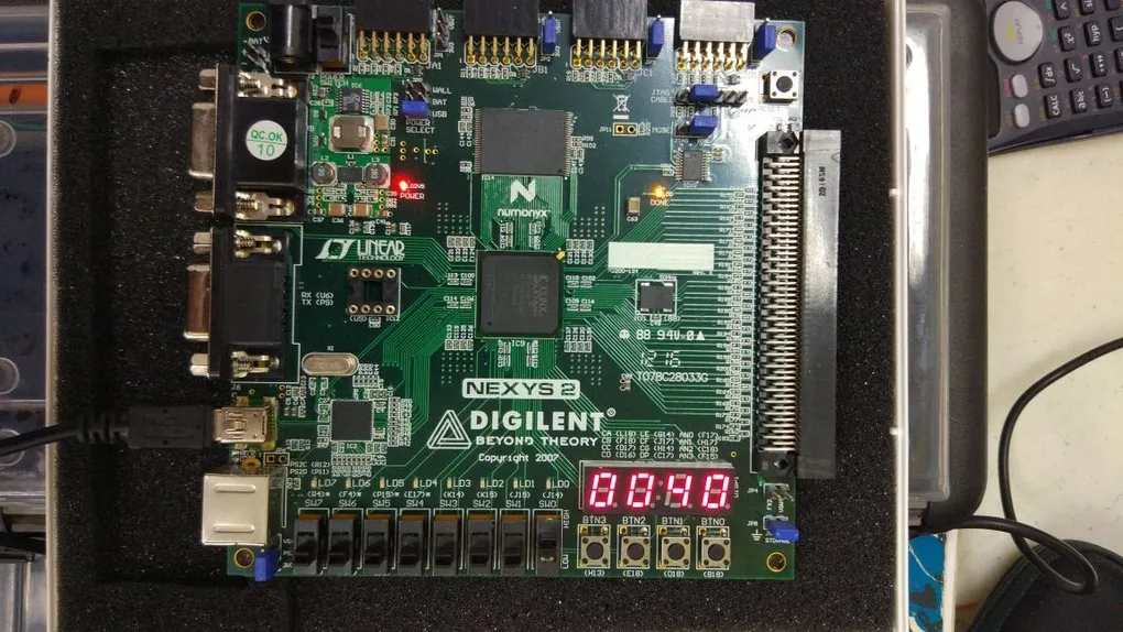
El resultado final es el siguiente: